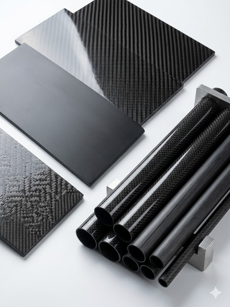


Ordering a custom carbon fiber tube requires more than providing a diameter and length.
Two tubes can share the same outer diameter, inner diameter and wall thickness but perform very differently because of changes in fiber orientation, resin system, manufacturing process and interface design. One may be optimized for bending stiffness, another for torsion, and another for repeated clamping or impact.
A useful specification must therefore connect the tube dimensions with its actual function.
Before requesting a quotation, define:
- What the tube does in the finished product
- How it is supported
- Where and how the load is applied
- Which dimensions control the assembly
- How the tube connects to other parts
- What environment it will operate in
- How performance will be verified
The Six Inputs a Carbon Fiber Tube Supplier Needs First
A supplier can review a project more accurately when the following information is available from the beginning.
| Requirement | Minimum Information to Provide |
|---|---|
| Application | What the tube does in the finished assembly |
| Geometry | OD, ID, length and available installation space |
| Load | Direction, magnitude, position and support condition |
| Interface | Insert, clamp, bearing, connector or telescopic fit |
| Environment | Temperature, UV, moisture and chemical exposure |
| Quantity | Prototype quantity and expected production volume |
When one of these inputs is unknown, identify it clearly rather than replacing it with a guess.
For example, instead of choosing an arbitrary wall thickness, a buyer can provide the maximum OD, working length, end load and acceptable deflection. The supplier can then evaluate an appropriate wall structure and layup for sampling.
1. Define the Application and Load Before Choosing Tube Dimensions
The first design question should not be:
What diameter tube do we need?
It should be:
What must the tube do in the final product?
Carbon fiber composites are anisotropic. Their properties depend strongly on fiber direction. The number, orientation and sequence of the plies form the laminate layup and determine how the tube responds to different loads.
A specification should therefore begin with the dominant load cases.
Axial Tension and Compression
Axial loads act along the length of the tube.
They are common in:
- Structural struts
- Push-pull rods
- Tripod legs
- Robotic linkages
- Lightweight frames
- Telescopic supports
Tubes carrying mainly axial loads normally benefit from a high proportion of fibers aligned with the tube axis.
However, longitudinal fibers alone may not be enough. Off-axis or circumferential reinforcement may still be required around clamps, drilled holes, bonded inserts and impact-prone areas.
For compression-loaded members, also provide:
- Unsupported length
- End conditions
- Expected compressive load
- Whether the tube is perfectly aligned
- Whether lateral movement is possible
A long tube may fail by buckling before the laminate reaches its material strength limit.
Bending
Bending is often the controlling condition in long tubes, poles, equipment handles, inspection masts and cantilevered supports.
The supplier should know:
- Working length
- Support condition
- Load position
- Load direction
- Maximum working load
- Acceptable deflection
- Whether the load is static or repeated
Avoid requirements such as:
The tube must be very stiff.
A more useful requirement is:
The tube will be fixed at one end, extend 1,500 mm horizontally and carry a 0.8 kg camera at the free end. Deflection must remain within the agreed limit.
This allows the supplier to evaluate the relationship between OD, wall thickness, axial fiber content and overall weight.
Increasing OD is often an efficient way to improve bending stiffness because it places more material away from the tube’s center. However, the available installation space, connector dimensions, nesting requirements and shipping limits may restrict the maximum diameter.
Torsion
Torsion twists the tube around its longitudinal axis.
It matters in:
- Drive shafts
- Tool handles
- Adjustable locking systems
- Robotic arms
- Rotary inspection equipment
- Tubes with offset end attachments
A tube containing mostly axial fibers may provide high longitudinal stiffness but insufficient torsional rigidity.
Angled plies, commonly arranged in balanced positive and negative directions, can be used to carry shear and torsional loads.
When torsion matters, specify:
- Maximum torque
- Direction of rotation
- Repeated or one-time loading
- Acceptable twist angle
- Connection method at both ends
- Whether torque reversal occurs
Radial Pressure and Local Crushing
Many carbon fiber tube problems occur at an interface rather than in the open span.
Typical risk areas include:
- Cam-lock collars
- Quick-release clamps
- U-bolts
- Bearings
- Press-fit components
- Bolted joints
- Bonded metal inserts
- Telescopic overlap zones
The supplier needs to understand:
- Clamp width
- Contact area
- Tightening method
- Expected clamping force
- Number of operating cycles
- Whether the clamp position changes
A narrow clamp can concentrate pressure and damage the laminate even when the tube is strong enough for the main bending or axial load.
For adjustable structures, existing carbon fiber telescopic pole configurations can help buyers understand how nested sections, overlap length and locking components affect tube geometry.
Impact, Vibration and Fatigue
A tube may also be exposed to conditions that are not visible in a simple dimensional drawing:
- Repeated extension and retraction
- Continuous vibration
- Accidental drops
- Tool impact
- Cyclic bending
- Locking and unlocking
- Transportation shock
- Abrasive contact
These conditions should influence the laminate design and test plan.
A tube for a fixed indoor frame does not require the same validation as a portable pole that is extended, clamped and transported every day.
Environmental Conditions
Provide the actual operating environment, including:
- Continuous service temperature
- Short-term temperature peaks
- Outdoor UV exposure
- Water or salt spray
- Cleaning agents
- Oil or fuel contact
- Dust and abrasion
- Electrical hazards
Carbon fiber is electrically conductive. A standard carbon fiber tube should not be considered electrically insulating unless the complete product has been specifically designed, tested and certified for that purpose.
2. Specify OD, ID, Wall Thickness and Length as One System
For a uniform round tube:
Wall thickness = (OD − ID) ÷ 2
This equation is simple, but the specification is not.
OD, ID, wall thickness and length affect different parts of the assembly and should be defined together.
Outer Diameter: OD
The outside diameter affects:
- Bending stiffness
- External installation space
- Clamp compatibility
- Bearing and collar fit
- Telescopic nesting
- Aerodynamic profile
- Overall weight
OD is usually the controlling dimension when the tube must fit inside an existing clamp, housing or machine assembly.
The drawing should also clarify which surface the OD applies to:
- As-cured structural surface
- Sanded surface
- Ground or machined surface
- Painted surface
- Clear-coated surface
- Decorative woven outer layer
Grinding and sanding remove material. Paint and clear coating add thickness. The measurement condition must therefore be agreed before production.
Inner Diameter: ID
ID becomes critical when another component must fit inside the tube.
Examples include:
- Aluminum inserts
- Threaded sleeves
- Bearings
- Electrical wiring
- Pneumatic lines
- Inner telescopic sections
- Spring-button mechanisms
- Bonding plugs
Do not state only:
The ID must fit a 20 mm insert.
Also provide:
- Actual insert diameter and tolerance
- Required insertion depth
- Bond-line requirement
- Sliding, bonded or interference fit
- Required pull-out or torque capacity
- Surface preparation method
For bonded inserts, a controlled adhesive gap is generally more predictable than an uncontrolled press fit. The correct bond-line thickness depends on the adhesive, insert design and surface preparation.
Wall Thickness
Wall thickness influences:
- Tube weight
- Axial capacity
- Bending behavior
- Local crush resistance
- Machining allowance
- Impact tolerance
A thicker wall does not solve every structural problem.
Depending on the failure mode, it may be more effective to:
- Increase OD
- Change fiber orientation
- Reinforce a local interface
- Increase overlap length
- Widen the clamp
- Change the insert geometry
A wall may be:
- Uniform along the full length
- Locally reinforced
- Machined near one end
- Different between telescopic sections
- Built with additional material around holes
- Covered by a cosmetic outer ply
For telescopic products, using the same wall thickness in every section can create unnecessary weight or poor stiffness distribution. Each section should be reviewed according to its diameter, overlap and load contribution.
Length
The length specification should include more than the nominal finished length.
Confirm:
- Finished overall length
- Length tolerance
- Square-cut or angled ends
- Bonding depth
- Insert depth
- Machined end length
- Telescopic overlap
- Usable extension
- Collapsed length
- Packaging length
Longer tubes can be more difficult to manufacture, inspect, machine and transport. Tooling and process limitations may also affect the maximum practical one-piece length.
For telescopic assemblies, maximum extended length alone is not enough. The supplier also needs the collapsed length, number of sections, minimum overlap, end load and acceptable movement between nested sections.
The 21 m carbon fiber telescopic pole project shows why tube diameter, section length, overlap, locking structure and tip load must be evaluated as one system.
Decide Which Dimension Is Functionally Critical
Not every dimension needs the same tolerance.
| Assembly Requirement | Likely Critical Dimension |
|---|---|
| Tube fits inside a machined housing | OD |
| Insert bonds inside the tube | ID |
| Tube nests into another tube | OD and ID |
| Wiring passes through the tube | Minimum clear ID |
| Weight must remain below a target | Wall thickness and layup |
| Shaft must meet a deflection limit | OD, wall thickness and axial layup |
| Clamp must lock without crushing | OD, wall structure and clamp design |
Identifying the functional dimension allows the supplier to select an appropriate manufacturing and finishing process without adding unnecessary cost.
Avoid Applying Tight Tolerance Everywhere
Composite tubes should not automatically receive the same blanket tolerances as machined metal parts.
Achievable tolerances depend on:
- Manufacturing method
- Diameter
- Length
- Wall construction
- Tooling condition
- Surface finish
- Secondary grinding
- Measurement method
A long structural tube may need tight dimensional control only at short interface zones.
A practical drawing can separate the tube into:
- General structural area
- Bearing seat
- Bonding area
- Clamping area
- Telescopic sliding area
- Cosmetic surface
- Machined end
Each zone can then have its own tolerance and finish requirement.
3. Define the Layup Around the Required Performance
The phrase “100% carbon fiber” does not describe structural performance.
A meaningful specification should address:
- Fiber orientation
- Fiber grade
- Resin system
- Laminate balance
- Manufacturing process
- Local reinforcement
What the Main Fiber Directions Do
Fiber angles are normally described relative to the tube axis.
| Fiber Direction | Main Contribution | Typical Use |
|---|---|---|
| 0° axial | Longitudinal stiffness and axial load capacity | Poles, beams, struts and long tubes |
| ±45° | Torsion and in-plane shear | Drive shafts, handles and twist-loaded structures |
| 90° hoop | Circumferential stability and splitting resistance | Clamps, joints and radial loading |
| Woven outer ply | Balanced surface reinforcement and appearance | Cosmetic finish and handling protection |
These are design principles rather than fixed recipes.
A long pole may require a high proportion of axial reinforcement for stiffness, but still need angled and hoop plies to handle torsion, clamping and impact.
Balanced and Symmetric Laminates
A balanced laminate contains corresponding positive and negative angle plies, such as +45° and −45°.
A symmetric laminate mirrors the ply sequence around the laminate mid-plane.
These arrangements can help reduce unwanted twisting, warping and coupling, but they do not replace application-specific engineering.
The final sequence must also consider:
- Surface finish
- Drilled holes
- Insert bonding
- Local clamping
- Impact exposure
- Manufacturing limitations
- Minimum practical ply thickness
Standard-, Intermediate- and High-Modulus Fiber
Higher modulus can increase stiffness, but it does not automatically provide the best complete solution.
Higher-modulus materials may:
- Increase cost
- Reduce strain to failure
- Require more careful handling
- Add limited value when geometry is the real constraint
Before specifying high-modulus carbon fiber, review whether the target can be reached by changing:
- OD
- Wall thickness
- Axial fiber proportion
- Support conditions
- Section length
The buyer should define the performance target rather than selecting an expensive fiber grade without a clear reason.
Useful targets include:
- Maximum deflection
- Minimum proof load
- Minimum failure load
- Target tube weight
- Torsional stiffness
- Fatigue life
- Impact condition
Resin System
The resin matrix holds the fibers in position, transfers load between them and influences environmental performance.
The supplier should know:
- Continuous service temperature
- Short-term heat exposure
- Outdoor UV requirement
- Water or chemical contact
- Flame or smoke requirements
- Adhesive compatibility
- Surface finish expectation
A tube used in room-temperature indoor equipment may not need the same resin system as a component exposed to heat, aggressive cleaning chemicals or continuous sunlight.
Manufacturing Process
Common carbon fiber tube processes include:
Roll Wrapping
Prepreg plies are arranged around a mandrel and cured under pressure. This process offers flexibility in fiber orientation and laminate design.
Pultrusion
Continuous fibers are pulled through a resin system and forming die. It is efficient for constant profiles with high longitudinal fiber content.
Filament Winding
Continuous reinforcement is wound around a mandrel at controlled angles. It is useful when hoop or angled reinforcement is important.
The buyer does not always need to select the process.
In many projects, it is better to define:
- Geometry
- Load
- Performance
- Surface
- Quantity
- Cost target
The supplier can then recommend a suitable manufacturing route.
4. Design the Interfaces, Finish and Validation Plan Early
A tube can meet its nominal dimensions and still fail if the interface has not been designed correctly.
Plan Inserts and Connectors Before Finalizing the Laminate
Provide the following information for every insert or fitting:
- Insert material
- Insert diameter
- Insertion depth
- Thread size
- Bond-line requirement
- Expected pull-out load
- Expected torque
- Operating temperature
- Surface preparation
- Mechanical retention method
For modular assemblies, custom threaded connectors for carbon fiber tubes can be designed around the tube ID, bonding depth, thread requirement and torque condition.
Review Holes and Fasteners
Drilled holes can interrupt load-carrying fibers and create stress concentrations.
The supplier should review:
- Hole diameter
- Hole position
- Edge distance
- Fastener type
- Washer or load-spreading feature
- Tightening torque
- Local reinforcement
- Required drilling quality
A hole placed too close to the tube end may initiate splitting. A fastener tightened directly against an unsupported laminate may cause local crushing.
Control Clamping Pressure
For clamps and collars, provide:
- Clamp width
- Contact geometry
- Fastening method
- Tightening torque
- Operating cycles
- Sliding or fixed position
- Required holding force
A wider contact area or reinforced clamping zone may be more effective than simply increasing the wall thickness of the entire tube.
Consider Galvanic Corrosion
Carbon fiber is electrically conductive and can contribute to galvanic corrosion when it contacts certain metals in a wet or conductive environment.
Possible protection methods include:
- Adhesive isolation
- Glass-fiber barrier layers
- Protective coatings
- Non-conductive sleeves
- Suitable metal selection
- Sealing against moisture
The solution should be chosen according to the actual environment and joint design.
Specify the Surface Separately from the Structure
A visible woven carbon pattern is often a cosmetic surface layer. It does not prove that the internal laminate uses the same fabric.
Common surface options include:
- Unidirectional carbon appearance
- 3K woven carbon
- Matte clear coat
- Glossy clear coat
- Sanded technical finish
- Painted finish
- Colored decorative layer
- Bond-ready surface
State whether the tube requires:
- Full cosmetic quality
- One visible cosmetic side
- Industrial surface quality
- Sliding contact
- Adhesive bonding
- Outdoor UV protection
This helps prevent disagreement over weave distortion, resin variation, sanding marks and minor surface defects that may not affect structural performance.
Agree on Inspection Before Production
Inspection requirements should match the application risk.
Possible checks include:
- OD and ID measurement
- Wall-thickness measurement
- Length inspection
- End squareness
- Straightness
- Weight verification
- Visual surface inspection
- Fit check with mating parts
- Insert pull-out testing
- Torsion testing
- Bending or deflection testing
- Lock-slippage testing
- Proof-load testing
For non-critical commercial products, dimensional, visual and functional checks may be sufficient.
Safety-critical applications require a project-specific validation plan prepared and approved by qualified engineers.
Example: Portable Camera Inspection Tube
The following example shows how application requirements can be converted into a useful preliminary specification.
| Item | Project Requirement |
|---|---|
| Application | Portable roof inspection camera |
| Working length | 1,500 mm |
| Support | Cantilevered from one end |
| End-mounted load | 0.8 kg |
| Maximum OD | 32 mm |
| Primary load | Bending |
| Secondary load | Handling and occasional torsion |
| End interface | Bonded aluminum camera mount |
| Surface | Matte woven carbon appearance |
| Initial quantity | 5 prototypes |
| Production volume | Approximately 500 pieces per year |
| Validation | Deflection, insert fit and pull-out testing |
At this stage, the buyer should not automatically choose the ID, wall thickness or layup.
Those values should be reviewed after confirming:
- Acceptable tip deflection
- Insert diameter
- Required bonding depth
- Expected handling load
- Target tube weight
- Safety factor
The supplier may then compare different combinations of OD, wall structure and axial reinforcement before producing samples.
This approach is more reliable than selecting a wall thickness from a standard tube catalog without considering the complete assembly.
5. Send a Complete RFQ and Validate the Sample
A clear RFQ reduces repeated questions and helps the supplier evaluate material, tooling, production process, lead time and cost.
Custom Carbon Fiber Tube RFQ Checklist
| Item | Information to Provide |
|---|---|
| Application | What the tube does in the final product |
| Drawing | 2D drawing, 3D model or dimensioned sketch |
| OD | Nominal value and tolerance |
| ID | Nominal value, minimum clearance or mating-part size |
| Wall thickness | Nominal value or performance-based requirement |
| Length | Finished length and tolerance |
| Quantity | Prototype and expected production volume |
| Load | Direction, magnitude and position |
| Support | Cantilevered, supported, clamped or other |
| Deflection | Maximum acceptable movement |
| Torsion | Maximum torque and allowable twist |
| Interface | Insert, clamp, bearing, sleeve or telescopic fit |
| Environment | Temperature, UV, moisture and chemicals |
| Surface | UD, woven, matte, glossy, painted or technical |
| Machining | Holes, slots, grinding, cutouts or bonding zones |
| Testing | Dimensional, functional or proof-load requirements |
| Packaging | Cartons, individual protection or long-tube crates |
An Incomplete RFQ
Please quote a carbon fiber tube, 30 mm diameter and 1,500 mm long.
This leaves important questions unanswered:
- Is 30 mm the OD or ID?
- What must fit inside the tube?
- What load will it carry?
- How is the tube supported?
- What deflection is acceptable?
- Does it experience torsion?
- Are inserts or holes required?
- What quantity is needed?
A Useful RFQ
We need a custom carbon fiber tube for a portable inspection device. The tube will be fixed at one end, extend 1,500 mm horizontally and carry a 0.8 kg camera at the free end. The maximum OD is 32 mm. One end requires a bonded aluminum insert and the opposite end requires two cross-drilled holes. Please recommend the ID, wall structure and layup after reviewing the deflection target and insert drawing. Initial sample quantity is five pieces, followed by an estimated annual requirement of 500 pieces.
This version gives the supplier enough information to begin a meaningful review.
Validate the Prototype Before Bulk Production
A sample should confirm more than appearance.
Depending on the project, check:
- Critical OD and ID
- Fit with mating components
- Finished weight
- Straightness
- Surface quality
- Deflection under working load
- Insert bond strength
- Clamp holding force
- Hole quality
- Repeated operation
- Packaging protection
Record the approved sample dimensions, test method and acceptance criteria.
The approved sample should not replace the drawing. Both should be used together as the production reference.
Frequently Asked Questions
Should I Specify Both OD and ID?
Specify both when they control different mating components. If only one dimension is critical, identify it clearly and allow the supplier to recommend the other based on the required wall structure.
Can I Specify OD and Wall Thickness Instead of ID?
Yes. The nominal ID can be calculated from OD and wall thickness. However, a separate ID tolerance is still necessary when an insert, bearing or inner tube must fit precisely.
Is a Thicker Carbon Fiber Tube Always Stiffer?
A thicker wall generally adds material, but it may not be the most weight-efficient solution. Increasing OD or changing the axial layup can produce a better stiffness-to-weight result in some applications.
Does a 3K Woven Surface Mean the Whole Tube Uses Woven Fabric?
No. A woven layer may be used only as a cosmetic outer ply. The internal structural laminate may use unidirectional or other reinforcement.
Do I Need to Design the Layup Myself?
Not necessarily. Most buyers can provide the application, geometry, load, interfaces and performance targets. The supplier can then recommend a preliminary laminate for sampling and testing.
When Is Prototype Testing Especially Important?
Testing is particularly important when the tube includes tight mating tolerances, bonded inserts, drilled holes, repeated clamping, significant bending, torsion or safety-related performance requirements.
Specify the Function, Not Only the Tube Size
A reliable custom carbon fiber tube specification connects four areas:
- Geometry: OD, ID, wall thickness and length
- Performance: Axial load, bending, torsion and radial pressure
- Interfaces: Clamps, inserts, bearings, holes and connectors
- Validation: Tolerances, inspection and functional testing
The most common sourcing mistake is fixing a diameter and wall thickness before defining how the tube will be supported, loaded and connected.
To request a technical review, send your drawing or dimensioned sketch together with the application, working length, load, interface dimensions, surface requirement and estimated quantity through the project inquiry page.
Send Your Tube Specification for Engineering Review
Include:
- Drawing or sketch
- Required OD or ID
- Finished length
- Load and support condition
- Insert or clamp details
- Prototype and production quantity
These details provide a practical basis for reviewing the tube geometry, laminate structure, manufacturing process and sample validation plan.